
What this system is
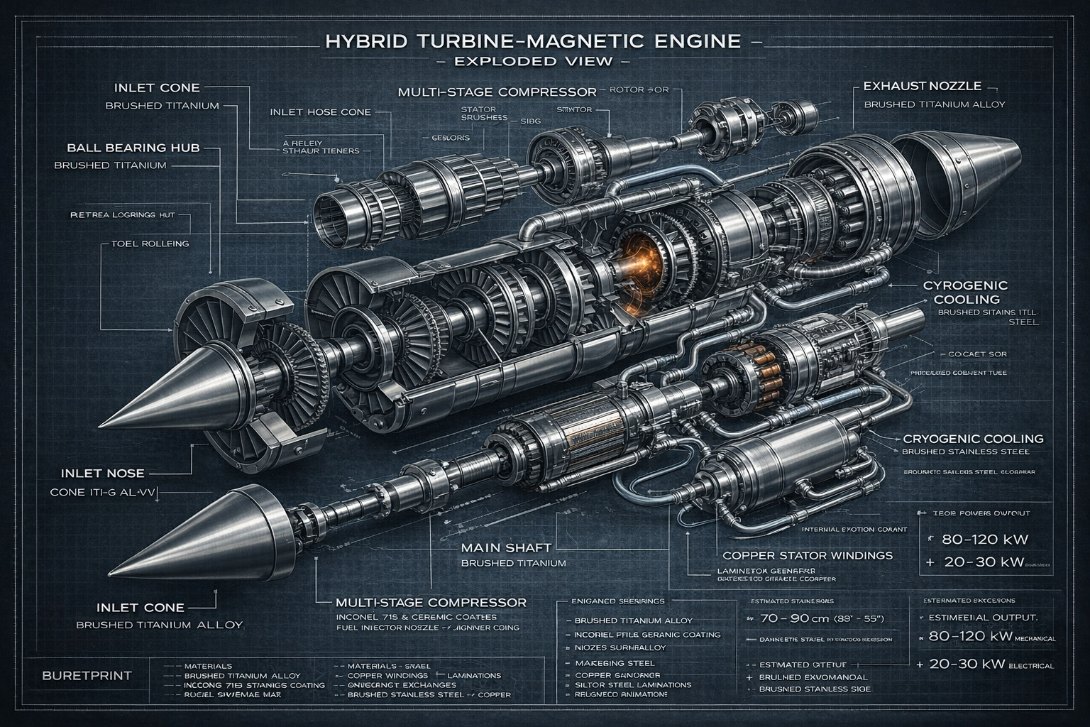
This program defines a compact hybrid turbine engine that couples a traditional Brayton-cycle gas turbine core (inlet → compressor → combustor → turbine → exhaust) to an integrated electromagnetic generator on a shared shaft, supported by a thermal management subsystem and a controls + power conditioning stack.
The goal is a single packaged unit that can deliver mechanical shaft power and/or regulated electrical output, with a clear documentation trail suitable for patent filings, engineering reviews, and future prototyping.
Program Objectives
-
Integrated turbine + generator packaging mechanical + electricalShared shaft architecture with reduced external coupling complexity.
-
Configurable electrical output DC bus, optional inverterRectification, regulation, distribution, and safe disconnect/precharge.
-
Thermal stability & serviceability cooling + sensorsThermal management loops for hot zones, generator, and power electronics.
-
Patent-ready documentation drawings + claimsFigures, reference numerals, claim sets, and alternative embodiments.
Ioncore media and downloadable patent packet
Shared engine renderings from the Ioncore brochure repository are included below, with direct access to the patent packet document for download.

System Architecture (High Level)
Subsystem Breakdown mechanical
- Inlet + IGV flow conditioningStabilizes airflow and sets compressor inlet angle.
- Multi-stage Compressor pressure ratioAxial stages (rotor/stator) compress air into combustor.
- Combustion Chamber energy addFuel injection + ignition + flame stabilization.
- Turbine Stage shaft powerExtracts energy from hot gas to drive the shaft.
- Exhaust / Nozzle flow controlDirects exhaust; may incorporate expansion and shielding.
Subsystem Breakdown electrical
- Generator (PM / Wound Field) 3-phaseRotor magnetic assembly + stator windings.
- Rectification + DC Link BR1 + Cbank3-phase bridge to DC_RAW with smoothing capacitors.
- Regulation DC-DC or shuntEstablishes DC_BUS and manages overvoltage across RPM.
- Distribution contactorsPrecharge + main contactor + external outputs.
- Sensors + ECU closed loopV/I/T/RPM monitoring, fault logic, safe shutdown.
Subsystem Breakdown thermal
- Coolant Loop pump + manifoldPumped circuit for generator/power electronics zones.
- Heat Exchanger rejectionTransfers heat to ambient air or secondary fluid loop.
- Instrumentation TEMP / FLOWThermocouples, flow, and pressure sensing for control.
What it does (Capabilities)
-
Power Generation electricConverts shaft power to multi-phase electrical output, then conditions it to a regulated DC bus. Optional inverter stage can provide AC output.
-
Mechanical Output shaft / thrust optionsTurbine core produces shaft rotation. Depending on integration, shaft can drive generator, pump, fan, or other mechanical loads.
-
Thermal Stabilization coolingMaintains component temperatures within operating windows, improving reliability and consistent output.
Standard Spec Placeholders (editable) update anytime
Electrical System (Patent Figure Set)
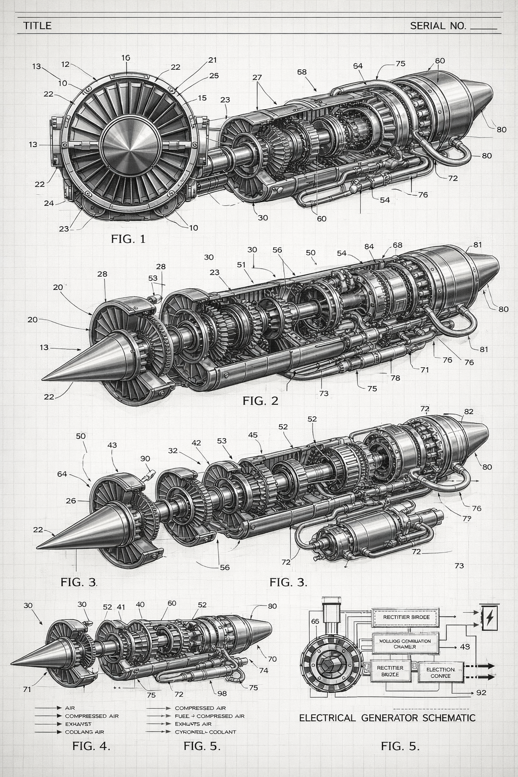
The electrical architecture is organized into patent figures FIG. 5A–5E, covering generation through regulation, distribution, control, and optional storage.
Net Naming Convention (recommended) CAD friendly
Thermal Management (What it’s designed to accomplish)
-
Protect high-temperature zones turbineThermal shielding and controlled heat transfer away from turbine-adjacent structures.
-
Stabilize generator + power electronics reliabilityCooling loop targets stator housing, rectifier, DC-DC, and contactor regions.
-
Enable consistent output controlSensor-driven pump/fan control to maintain stable operating temperatures.
Cooling Options (Embodiments) expandable
- Liquid loop pump + HXMost practical for compact packaging.
- Air ducting simplerLower complexity, less heat flux capability.
- Advanced fluids / insulated lines optionalFor higher thermal gradients and specialized use cases.
Roadmap (Development Plan)
Phase 1 — Definition now
- Lock baseline architectureFinalize subsystem interfaces, reference numerals, and figure set.
- Finalize BOM / realistic parts listManufacturable components, materials, and assembly groupings.
- First-order performance modelingBrayton-cycle estimate + generator/power conditioning estimates.
Phase 2 — Engineering Validation next
- Map-based performance modelCompressor/turbine maps, transient operation, surge margins.
- Thermal modelHeat loads, coolant sizing, electronics thermal derating.
- Controls and protection logicStartup/shutdown sequencing, fault handling, regulation stability.
Phase 3 — Prototype Path future
- Test plan + instrumentationRPM, EGT, pressures, bus voltage/current, vibration.
- Mechanical validationRotor dynamics, balancing, bearing selection, containment.
- Electrical validationRectifier heating, regulation ripple, load transients, EMI.
Deliverables (What exists / what this program produces)
-
Patent-style diagram set FIG. 1–5EFront view, side cutaway, exploded assembly, airflow diagram, electrical schematic figures.
-
Engineering BOM + parts lists manufacturableAssembly codes, realistic materials, sensors, and power electronics components.
-
Patent packet PDFDefinitions, detailed description, alternative embodiments, methods, reference numerals, and expanded claim set.
-
Simulation notes first-orderCapability estimates with a plan for higher fidelity modeling.
